RecommendMail Facebook LinkedIn
Rely on high-precision F-Theta lenses from Jenoptik
For demanding applications in laser material processing
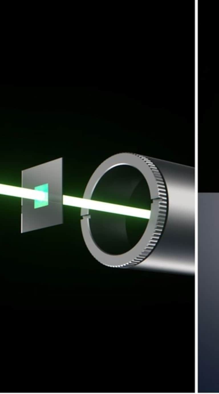
Lasers are ideal tools when it comes to processing materials such as plastics, metals or other substrates quickly and efficiently. Typical applications include laser drilling, laser cutting, laser polishing, laser marking or laser structuring to change the function of a surface.
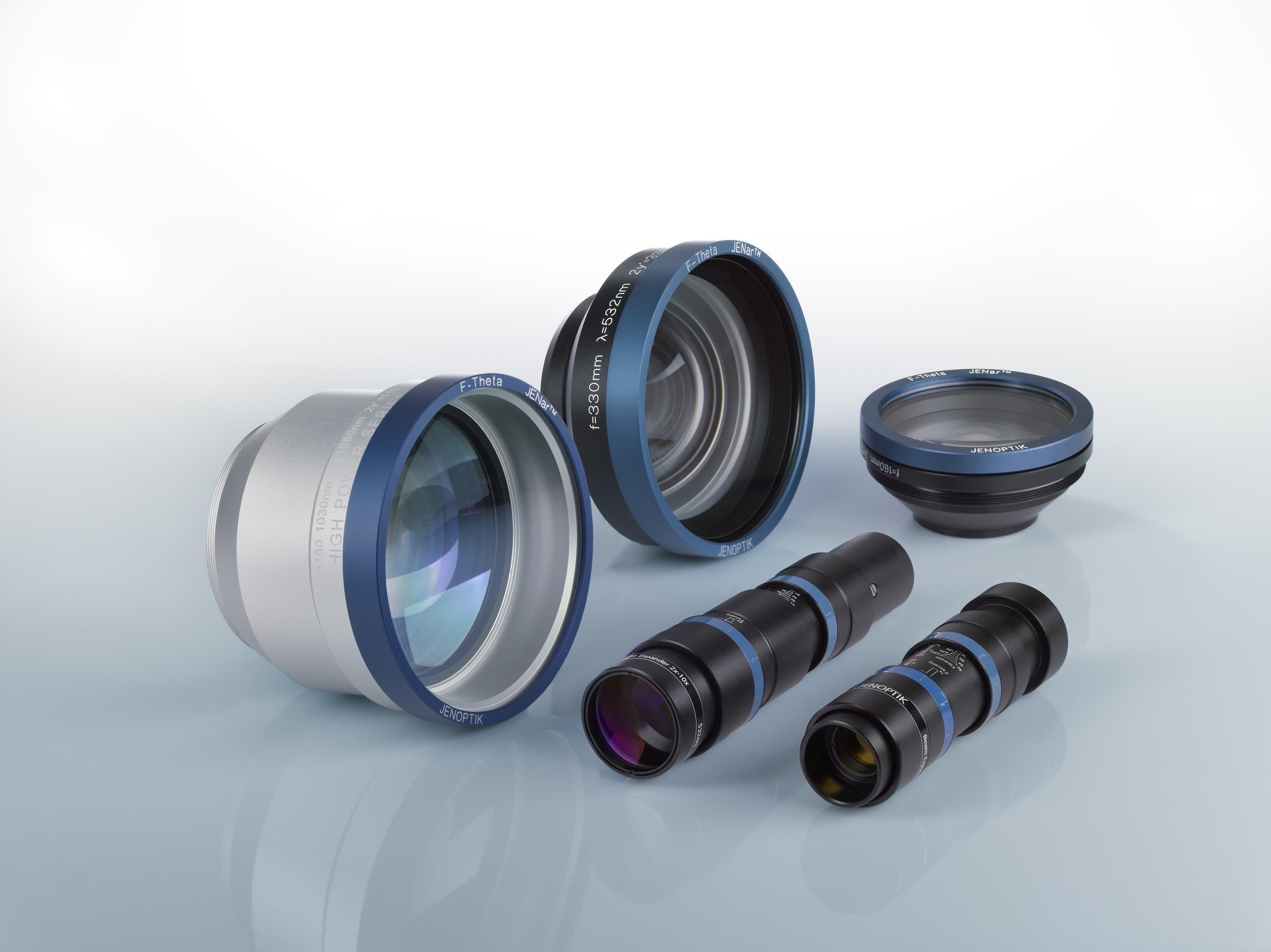
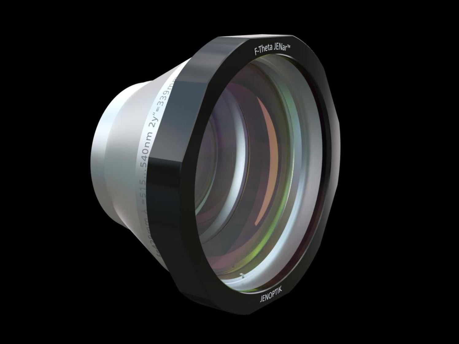
We offer a wide range of F-theta lenses for different applications and laser types. For medium and high-power laser material processing, we have developed the JENar™ lenses, available from 355 to 1080 nm. The JENar™ Silverline™ all-quartz lenses, available for 266 to 1100 nm, are ideal for high power and short pulse lasers. The JENar™ APTAline™ series completes our portfolio with a cost-effective solution designed for reliability and longevity, available from 355 to 1080 nm.
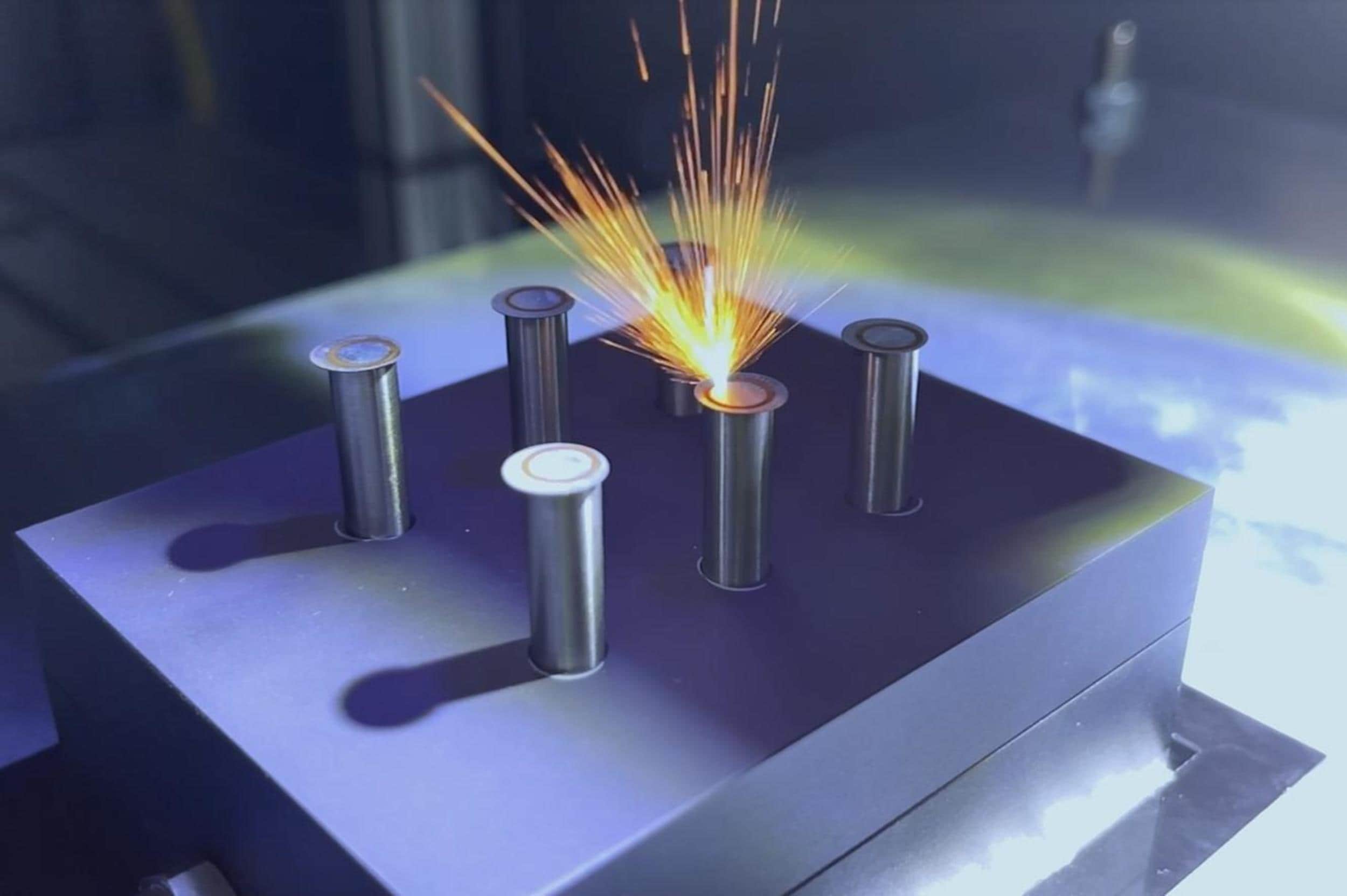
NEW: Discover our objective lens for 3D-Printing/ Selective Laser Sintering
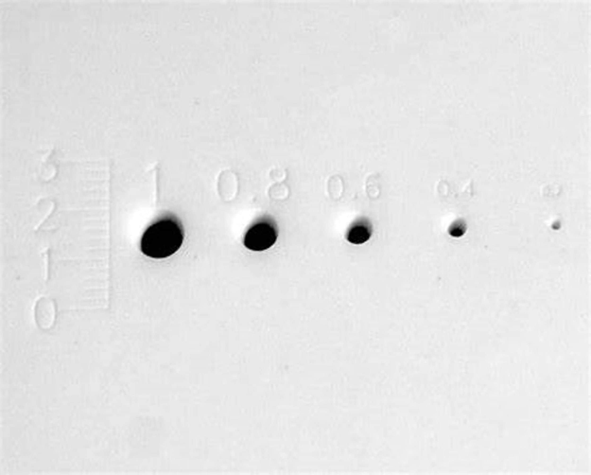
Maintain stable processes and achieve highly accurate geometries with Jenoptiks F-Theta JENar APTAline 639-1030…1080-580-AL. Designed for wavelength of 1030…1080 nm and with a focal length of 639 mm it is made for high-precision laser processing technologies like Selective Laser Sintering (SLS). The new objective has a scan field of 410mm x 410mm and provides excellent homogeneity across the entire field thanks to its advanced optical design.
More highlights are:
- Reliable high-quality
- High-precision results
- Minimized back-reflections
- High beam stability
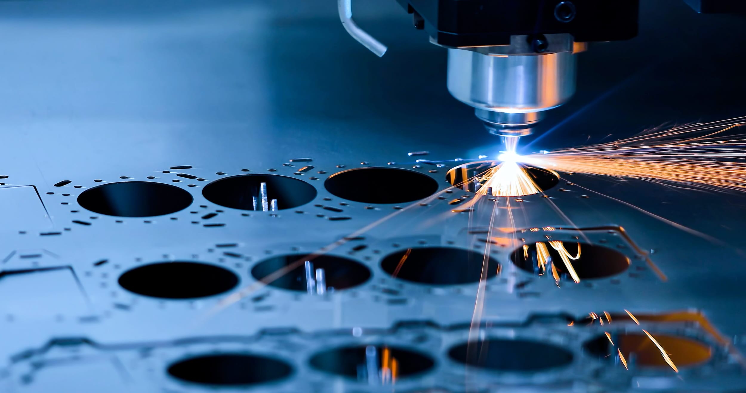
Enabling increased productivity and accurate results across industries
How do you increase process efficiency in solar cell production and achieve stable process quality?
Among other things, by using high-precision F-Theta lenses that are adapted to the requirements. Jenoptik offers customized high-performance lenses that have a larger scan field, extended focus lengths and a robust design.

Reliable multi-tasking talents made for high-volume laser applications
Our years of expertise in optics, our competencies in development, manufacturing, coating, assembling and testing makes Jenoptik to one of the leading providers for F-Theta lenses and components around. We deliver high-performance from single component to systems made for typical application tasks, like:
- Laser welding
- Laser cutting
- Laser marking
- Laser cleaning
- Laser drilling
- Micro structuring/ Micro scribing
Get rid of complex optical set-ups wasting your time and money in solar manufacturing process!
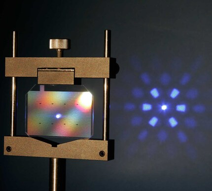
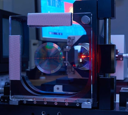
Try our Modular Beam Splitting System MBSS:
- Combines micro-optics & optics in one subsystem
- Ready-to-integrate and customizable set-up
- Parallel processing for more